How To Do Erd Diagram
Name the ERD as BikeShop and press OK to create the blank ER diagram. When documenting a system or process looking at the system in multiple ways increases the understanding of that system.

How To Draw An Er Diagram Lucidchart
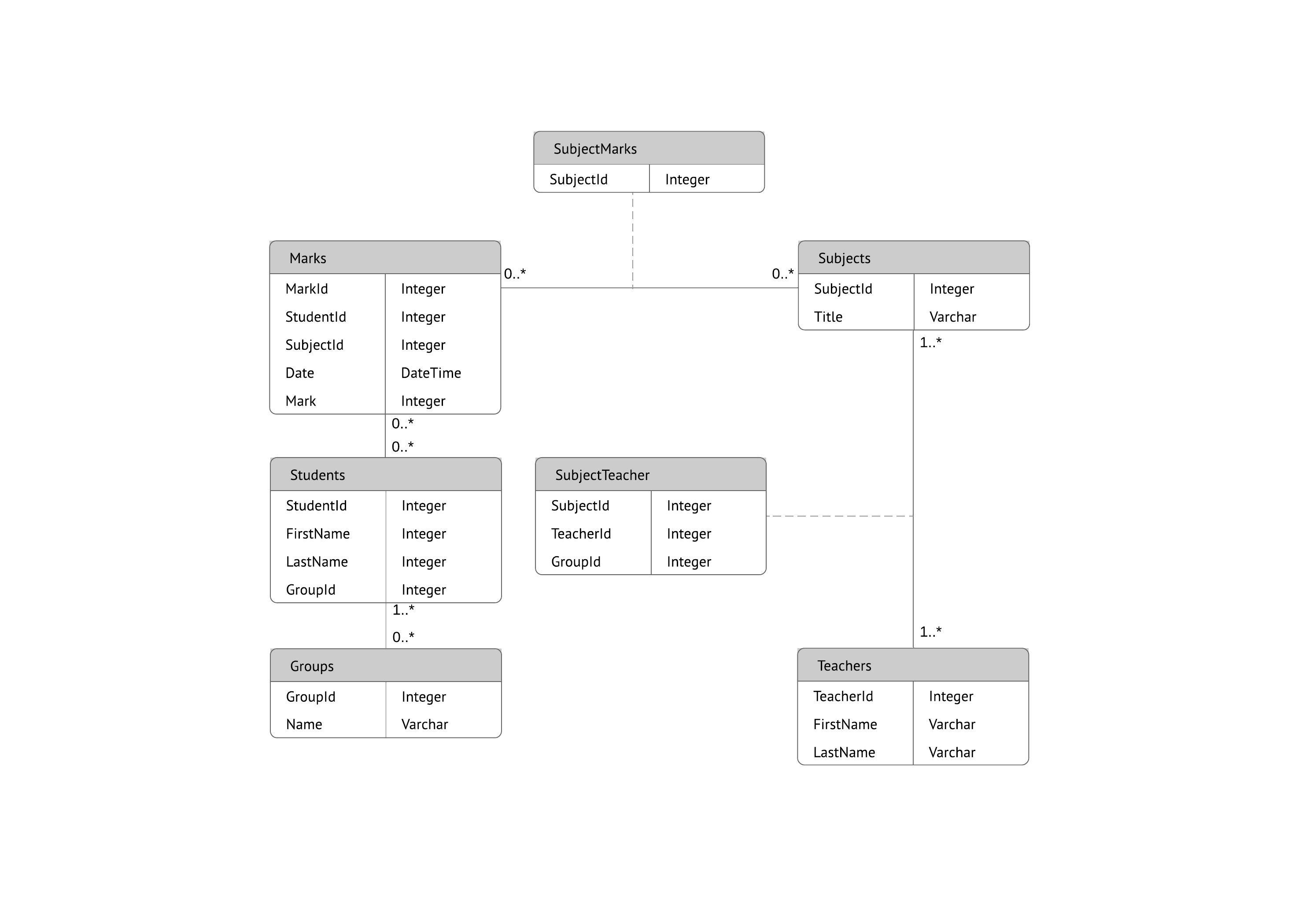
How To Create An Entity Relationship Diagram Using Conceptdraw Solution Park Entity Relationship Diagram Erd Er Diagram Of Student Teacher Library Department

Entity Relationship Diagram Erd Er Diagram Tutorial
6When you go Next and.
How to do erd diagram. They help us to visualize how data is connected in a general way and are particularly useful for constructing a relational database. An entity relationship diagram ERD is a diagram that defines the structure of database instances. Click Next and go to Select Objects menu.
With dedicated shape libraries drag and drop standard ERD symbols onto the canvas within seconds. The major entities within the system scope and. Here you can find some useful information about each notation.
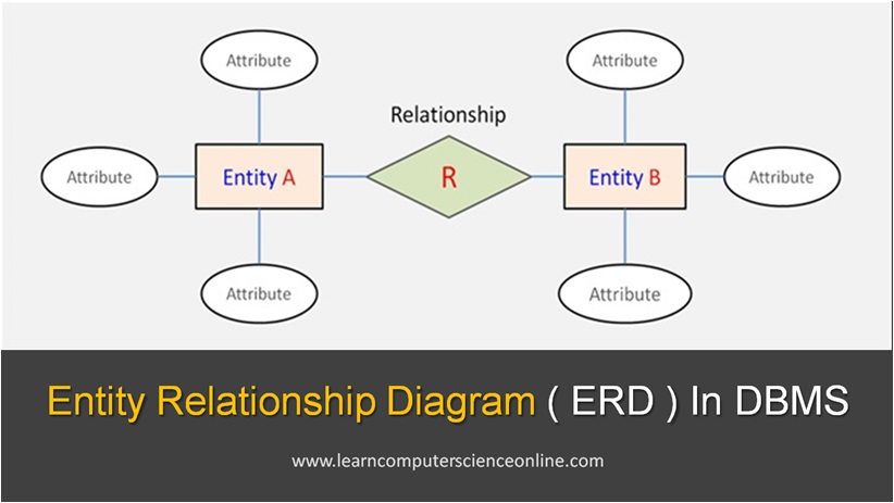
CASE tool for diagrams software design analysis Software Ideas Modeler is a smart CASE tool and diagram software that supports UML SysML ERD BPMN ArchiMate flowcharts user stories wireframing for those who love to develop great software. The highest level of abstraction for the data model is called the Entity Relationship Diagram ERD. The entity-relationship model or ER model is a way of graphically representing the logical relationships of entities or object s in order to create a database.
The visibility modifier can be used to identify mandatory attributes. It is a graphical representation of data requirements for a database. Learn how to create an Entity Relationship Diagram in this tutorial.
A space can be used after the modifier character to. Is a reference and description of each data element. See this article right now to explore more about the ER Diagram field including advantages usages and how-to tips.
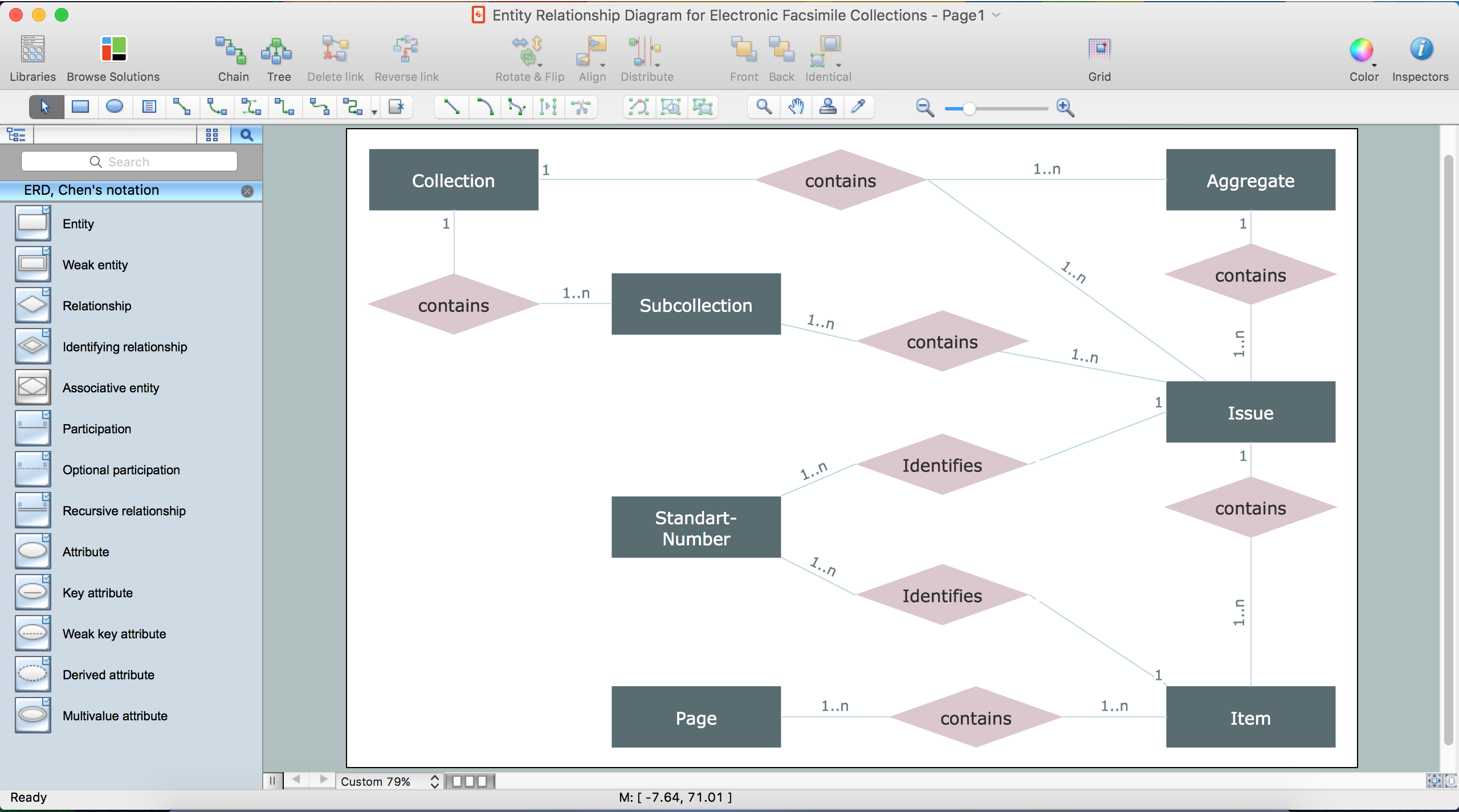
Our ER diagram tool simplifies database modeling whether your ERDs are conceptual or physical. You can create any entity-relationship diagram ERD by means of ConceptDraw DIAGRAM using ready-to-use templates and special libraries containing all the needed symbols and shapes. Anything that you can do in a class diagram can be done here.
Go to Diagram New to open the New Diagram dialog. Data model may be represented in many forms such as Entity Relationship Diagram or UML Class Diagram. ERD Case Study Examples with solution for a university management system will help you understand how to translate a business scenario into database exampleExciting stuff today people.
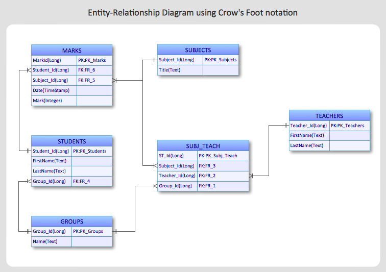
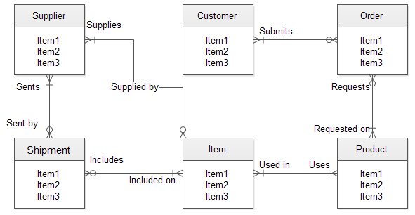
Find out what symbols are used in the Entity-Relationship Diagram ERD and what they mean. Entity Relationship Diagram Examples Crows Foot and Chens notation examples. Select Entity from the diagram toolbar.
Choosing which notation to use is typically left up to personal preference or conventions. Note we ARENT describe WHAT a post looks like Post relevant-to 1 to n Categories etc. In this article I am going to show you architecting data structures using the data modelling technique Entity Relationship Diagram with Crow Foot Notation.
Again this is the normal class diagram syntax aside from use of entity instead of class. Entity Relationship Diagram also known as ERD ER Diagram or ER model is a type of structural diagram for use in database design. ERD entity relationship diagram designed to show the logical structure of databases.
Today we are actually going to get our hands-dirty and do a hands-on practice for designing a database management system by creating ERD Case Study for University Management System. Creating the entity-relationship ER model by visually representing the structure of some database mainly the business one which data equates to its entities or objects that are connected by relationships showing requirements and dependencies you need proper software to provide you with the symbols necessary. Entity-relationship model ERM or ER model.
We provide a basic overview of ERDs and then gives step-by-step training on how to make. ER diagrams are best created with the use of proper and powerful diagram tools. The main value of carefully constructing an ERD is that it can readily be converted into a database structure.
Member Post Comment Category. Entities represent specific concepts or elements involved in a database. ERDs can and do include lines which denote nn relationships but this is not a requirement.
An ERD contains different symbols and connectors that visualize two important information. These can further have specific attributes that further define the overall properties of that said entity. An entity relationship diagram ERD is a structural diagram that allows your team to portray relationships between actors in a system.
There are three components in ERD. Creating a model for your database from now on can take just a few minutes. There are many techniques that are in use among data architects for designing data models such as Entity Relationship Diagram ERD and Data Matrix etc.
Here you can click on Show Filter to use the selected Table Objects in the diagram. An entity relationship diagram ERD is a popular type of database diagram that clearly displays the system entities and their internal relationships. Lucidchart is the essential ERD tool to quickly differentiate relationships entities and their attributes.
Lets start model our bike store database with ERD. This type of diagram is. It is the table you want to create the ER diagram of.
Enter erd in the search box to locate the Entity Relationship Diagram. The ER model was first proposed by Peter Pin-Shan Chen of. An Entity Relationship Diagram ERD is a visual representation of different entities within a system and how they relate to each other.
Learn how to create an Entity Relationship Diagram with Primary Keys Foreign Keys and Composite Keys in this advanced ERD tutorial. An Entity Relationship Diagram ERD is a data model describing how entities or concepts or things relate to one another. Model your database with ERD.
Press Next to proceed. You can both add and remove tables hereThen click on Execute. The Entity Relationship Diagram or ERD is set to help and understand the correlation between the entity sets that are available in a database.
When created by business analysts or business users ERDs can be used to understand the business domain clarify business terminology and connect business concepts to database structures. When you need to create an ER diagram to document a database it will be much easier using pre-made symbols and icons. For example the elements writer novel and a consumer may be described using ER diagrams the following way.
It is a detailed definition and documentation of data model learn more about data dictionary. ERD diagrams are commonly used in conjunction with a data flow diagram to display the contents of a data store. Examples of entities in an ERD for a blog.
Examples of relationships described in an ERD. Member posts 1 to n Posts. This page gathers many useful symbols that often used in ER diagrams Chen ERD Express-G diagram ORM diagram Martin ERD and database model diagram.
The most popular notation in ER diagrams is the Information Engineering IE notation also called crows foot notationThis is the default ER diagram notation used in Vertabelo.
Entity Relationship Diagram Erd Explained Er Model In Dbms
How To Make An Er Diagram Online Edrawmax Online
Drawing Er Diagrams On A Mac Entity Relationship Diagram Software For Mac What S The Best Erd Tool For The Mac Erd Draw For Mac
Er Diagram Erd Tool Lucidchart
Class
1

Developing An Application
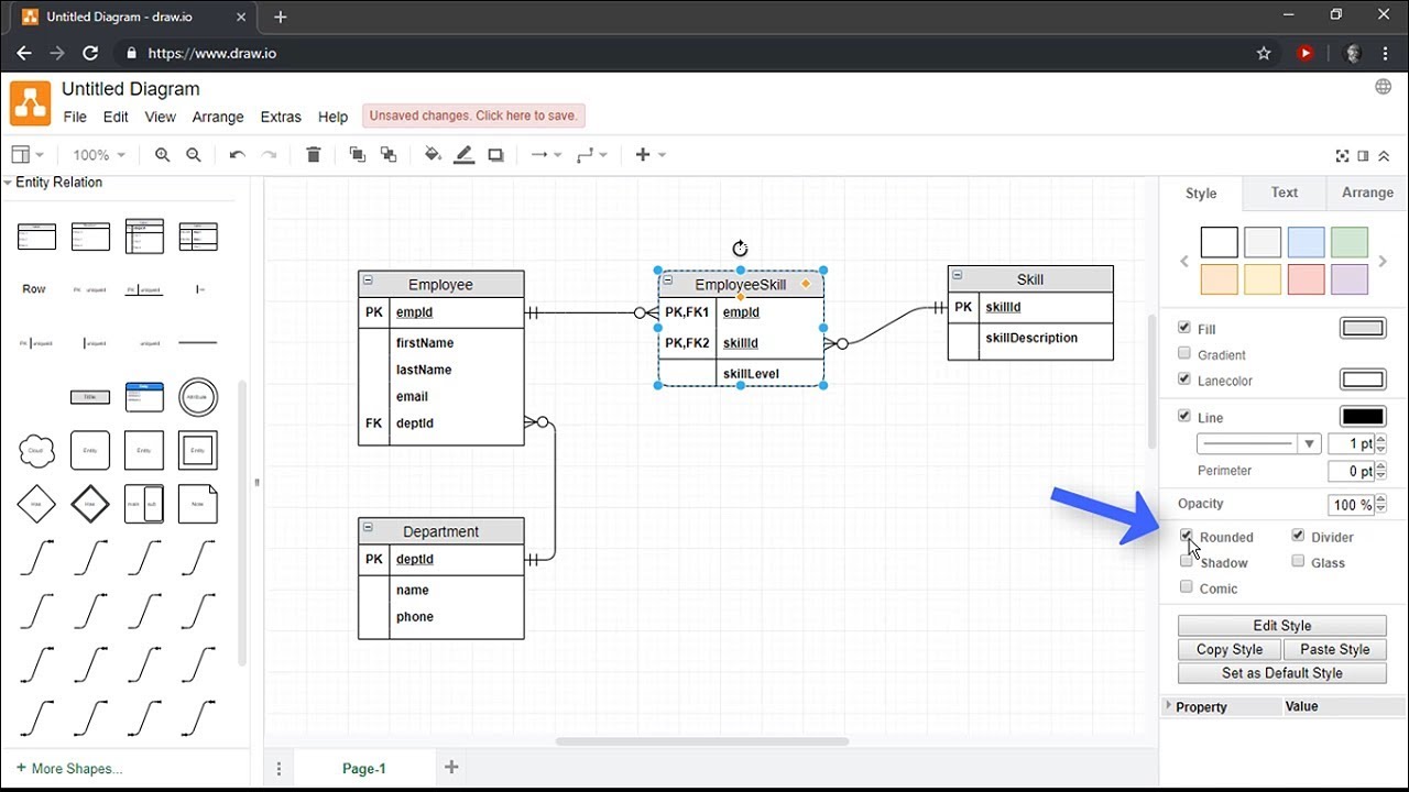
Creating Entity Relationship Diagrams Using Draw Io Youtube
Komentar
Posting Komentar